ALARM
DESCRIPTION
| The
chart recorder is equipped with an alarm system which is activated
when the sensor conditions exceed user-set limits. The system
consists of a built-in audible piezo-electric beeper and a set
of normally open dry relay contacts for activating an external
alarm. The contacts are rated for 2 amps at 110Vac or 2 amps at
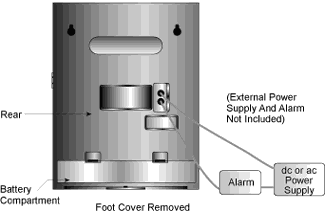
30Vdc. The contact terminals are mounted on the rear of the recorder
(refer to Figure 4-1). In addition, the LCD display will flash
upon alarm activation. |

Figure 4-1. Alarm/Relay Contacts Location
|
Checking
Alarm Limits
WAIT UNTIL THE UNIT
HAS STABILIZED AND THE PENS STOP MOVING BEFORE PRESSING ANY KEYS ON THE
KEYBOARD.
Depending on the Display Selection Switch position, the display will
be in ░C or pH for the alarm limit viewing.
The word æhiÆ and the high limit value of the alarm may be seen on
the display after pressing the ôHIGHö button on the front panel.
The word æloÆ and the low limit value of the alarm may be seen on
the display after pressing the ôLOWö button on the front panel.
NOTE: The alarm
limits are stored in permanent EEPROM memory and will not be lost even
if power is interrupted and battery backup fails.
Unlocking/Locking
the Control Panel Door
To
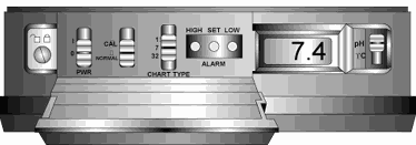
access the Alarm Display Buttons (Figure 1-1, item #10) under
the control panel door, you may have to unlock the door. YouÆll
find the control panel door lock to the left of the control panel.
Refer to Figure 4-2.
|

Figure 4-2. Location of the Door Lock
|
|
Unlocking
the Control Panel Door
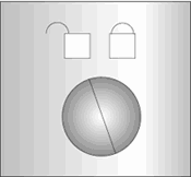
Use a small screwdriver to turn the lock to the left as far as
it will go. Figure 4-3 shows the unlocked position.
 Figure
4-3. Door Unlock Position
|
Locking
the Control Panel Door
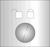
Use a small screwdriver to turn the lock to the right as far as
it will go. Figure 4-4 shows the locked position.

Figure
4-4. Door Lock Position
|
Setting/Changing Alarm Limits
 Figure
4-5
Alarm Display Buttons (HIGH/SET/LOW)
|
To set the alarm
limits on the alarm recorder:
1. Set
the display selection switch (Figure 1-1, item #12) to pH or ░C, depending
on the parameter for which you would like to set the alarm limits. Refer
to Figure 3-8 for the location of the switch.
2. Open the control panel door (unlock it, if necessary).
3. Press the ôSETö button to activate the display to set
either the high OR low alarm limit. At this time, ôSEö is displayed.
Figure 4-5 shows the location of the Alarm Display Buttons.
4. Release
the ôSETö button. The display will alternately flash ôhiö and ôloö
repeatedly.
5a. To change the high alarm limit:
- Press and hold
the ôHIGHö button for 4 seconds, then release. æhiÆ is displayed and
then the current high alarm limit is displayed.
- Press the ôHIGHö
or ôLOWö button to respectively increase or decrease the value.
- Press the ôSETö
button to lock in the value(s); the display now shows ôSAö.
5b. To change the low alarm limit:
Press and hold the ôLOWö button for 4 seconds, then release. æloÆ
is displayed and then the current low alarm limit is displayed.
Press the ôHIGHö or ôLOWö button to respectively increase or decrease
the value.
Press the ôSETö button again to lock in the value(s); the display
now shows ôSAö.
NOTE: If, after about 15 seconds, you donÆt press the ôSETö button
to enter the desired value, the alarm recorder returns the display to
the normal operation.
You can double check your limits at any time by pressing the ôHIGHö and
ôLOWö buttons.
6. Go through steps 1-5 to check and/or change the limits for the
other parameters. For example, if you already checked or changed ░C, you
may check or change pH if you choose.
7. After you are all done with the changes, close and lock the
control panel door, if necessary.
Turning the Alarm Off
If the high or low alarm limit for pH or temperature is exceeded, you
will hear the alarm. In addition, if the unit is operating under battery
power and the batteries are about to fail, you will hear the alarm.
The alarm will stay on even after the condition which caused the alarm
disappears. Refer to the example below:
|
Temp
High Limit
|
Actual
Temp.
|
Alarm
Sounding
|
|
75░
|
74░
|
OFF
|
|
75░
|
75░
|
ON (temp rises)
|
|
75░
|
74░
|
ON (temp drops) ***
|
***The alarm stays
on even though the temperature drops below the limit. The alarm recorder
will not reset automatically.
1. Unlock the control panel door if necessary.
2. After the alarm becomes activated, the ôSETö button must
be pressed to disable it.
The message ôAOö appears in the display. The alarm is disabled
for 10 seconds. After 10 seconds, the alarm may activate again, but only
if an alarm condition is present.
If the alarm is activated and you wish to change the alarm limits:
a. Press the ôSETö button for 5 seconds. First ôAOö,
then ôSEö message will appear in the display.
b. You can now proceed with the changing the alarm limits as described
in Section 4.4.
c. After you are all done with the changes, lock the control panel
door if necessary.
Disabling the Alarm
1. Unlock the control panel door if necessary.
2. On power up, when you hold the ôLOWö button down, an
ôAOö message appears in the display and the beeper sounds. This
will disable the alarm function.
(This action sets the high pH limit to 121, the low pH limit to 01, the
high temperature limit to 99, and the low temperature limit to 01. Since
these limits are outside the normal measuring range of the alarm recorder,
the alarm function is effectively disabled.)
The alarm limits are set this way when you receive the unit. If the
alarm is disabled, you must re-initialize the instrument. After you
are done with the changes, lock the door if necessary.
3. To verify the settings after re-initializing is completed, press
the ôLOWö button to get the low value, and the ôHIGHö button
to get the high value.
|